Questions on Eddy Currents, Generators and Inductance, the kind your examinations ask. Solve one on paper. Then tell the book how it went. The book believes you, and it uses your answer to plan your revision.
0%
Nothing marked yetMark honestly. Peek at the answer only after your own attempt.
Eddy Currents, Generators and Inductance
24 questions · after Lesson 4, Energy in an Inductor and Mutual Inductance
Eddy currents
Q1
What are eddy currents? How are they produced in a block of metal?
Answercirculating currents in bulk metal; changing flux through it
Solution
Eddy currents are closed loops of current that circulate inside a solid piece of conductor, like eddies in water. They are induced whenever the magnetic flux through the metal changes, either because the field changes or because the metal moves through a non-uniform field.
How did it go?
Q2
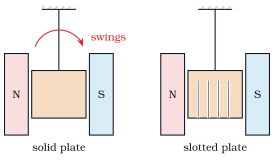
Both plates are set swinging between the poles.
Why does the solid plate stop within a few swings?
Why does the slotted plate keep swinging much longer?
Answer(i) eddy currents oppose the motion, energy to heat (ii) slots break the current paths
Solution
As the plate enters and leaves the gap, the flux through it changes and eddy currents flow. By Lenz's law these currents oppose the motion, so the plate feels a drag and its kinetic energy is turned into heat in the metal.
The slots cut across the paths the eddy currents would take, so only small loops can form and the currents are much weaker. The drag is small and the plate swings on.
Magnetic braking of trains and rotating machines. Induction furnaces, where eddy currents melt the metal. Damping of the coil in a dead-beat galvanometer. Also the speedometer of a vehicle and induction cooking.
How did it go?
Q4
Why are the iron cores of transformers and motors made of thin laminations separated by insulation?
Answerto cut eddy currents and heating
Solution
A solid core would carry large eddy currents driven by the changing flux, wasting energy as heat. Laminations with insulating layers between them break the core into thin sheets, confining any eddy current to a small area. The currents and the losses are greatly reduced.
How did it go?
Q5
An aluminium ring rests on the vertical iron core of a coil. When alternating current is switched on, the ring jumps up. Explain.
Answerinduced current in the ring opposes the coil's; repulsion
Solution
The alternating current makes a changing flux through the ring, inducing a current in it. By Lenz's law the induced current opposes the change, so the ring and coil act like two coils carrying opposite currents and repel. The upward force throws the ring off the core.
How did it go?
AC generator
Q6
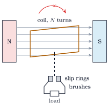
The coil of \(N\) turns and area \(A\) turns at \(\omega\) in the field \(B\).
Derive the emf \(\varepsilon = NBA\omega\sin\omega t\).
What do the slip rings and brushes do?
Answer(i) \(\Phi = NBA\cos\omega t\), \(\varepsilon = -\frac{d\Phi}{dt}\) (ii) connect the turning coil to the fixed circuit
Solution
The flux through the coil is \(\Phi = NBA\cos\omega t\), since the angle between the normal and \(\vec B\) grows as \(\omega t\). Faraday: \(\varepsilon = -\dfrac{d\Phi}{dt} = NBA\omega\sin\omega t\), an alternating emf.
The slip rings turn with the coil and the brushes press on them. The rotating coil thus stays connected to the fixed external circuit without the leads twisting.
How did it go?
Q7
A generator coil has \(200\) turns of area \(0.05\) m\(^2\) in a field of \(0.2\) T and turns at \(50\) Hz. Find the peak emf and the rms emf.
For the generator of Q7, find the emf at \(t = \frac{1}{600}\) s after the coil's plane is perpendicular to the field.
Answer\(100\pi \approx 314\) V
Solution
\(\omega t = 100\pi \times \dfrac{1}{600} = \dfrac{\pi}{6}\). \(\varepsilon = 200\pi\sin\dfrac{\pi}{6} = 100\pi \approx 314\) V.
How did it go?
Q9
At which positions of the coil is the emf greatest, and at which is it zero? Relate this to the flux.
Answergreatest when the plane is along \(\vec B\) (flux changing fastest); zero when perpendicular
Solution
The emf is largest when the plane of the coil is parallel to the field: the flux is zero there but changing fastest. It is zero when the plane is perpendicular to the field: the flux is greatest but momentarily not changing.
How did it go?
Q10
List the ways of doubling the peak emf of a generator.
Answerdouble \(N\), \(A\), \(B\) or \(\omega\)
Solution
Peak \(= NBA\omega\). Double the number of turns, the area, the field, or the speed of rotation. Doubling the frequency also halves the period, so the emf alternates twice as fast.
How did it go?
Self-inductance
Q11
Define self-inductance in two ways and give its unit. Write the induced emf in terms of \(L\).
Answer\(\Phi = LI\) or \(\varepsilon = -L\frac{dI}{dt}\); henry
Solution
Self-inductance is the flux linkage per unit current, \(\Phi = LI\), or the emf induced per unit rate of change of current, \(\varepsilon = -L\dfrac{dI}{dt}\). Its unit is the henry: \(1\) H \(= 1\) Wb/A \(= 1\) V s/A.
How did it go?
Q12
A solenoid has \(1000\) turns per metre, cross-section \(10^{-3}\) m\(^2\) and length \(0.5\) m. Find its self-inductance. Take \(\mu_0 = 4\pi \times 10^{-7}\).
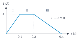
\(\dfrac{dI}{dt} = \dfrac{4}{0.2} = 20\) A/s, so \(|\varepsilon| = 4\) V. The current is falling, so this emf tries to keep it going: opposite in sense to that of stage I.
How did it go?
Q14
Find the energy stored in the inductor of Q13 while the current is \(4\) A.
Why does a spark jump at the switch when a circuit containing a large inductor is opened?
Answerlarge \(\frac{dI}{dt}\) gives a large emf across the gap
Solution
Opening the switch tries to stop the current almost instantly, so \(\dfrac{dI}{dt}\) is very large. The inductor's emf \(L\dfrac{dI}{dt}\) is then large enough to break down the air in the gap. The stored energy \(\dfrac{1}{2}LI^2\) is released in the spark.
How did it go?
Mutual inductance
Q18
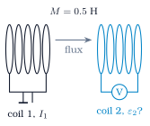
Define mutual inductance. Write the emf induced in coil 2 when the current in coil 1 changes.
Mutual inductance \(M\) is the flux linked with coil 2 per unit current in coil 1: \(\Phi_2 = MI_1\). When \(I_1\) changes, \(\varepsilon_2 = -M\dfrac{dI_1}{dt}\).
How did it go?
Q19
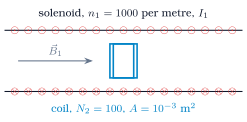
The coil sits on the axis of the long solenoid.
Find the flux linked with the coil per ampere of \(I_1\).
Find \(M\).
Answer(i) \(\approx 1.26 \times 10^{-4}\) Wb (ii) \(\approx 1.26 \times 10^{-4}\) H
Solution
\(B_1 = \mu_0n_1I_1\) inside. Flux linkage with the coil per ampere: \(N_2B_1A = \mu_0n_1N_2A = 4\pi \times 10^{-7} \times 1000 \times 100 \times 10^{-3} \approx 1.26 \times 10^{-4}\) Wb.
\(M\) is this flux linkage per ampere: \(M = \mu_0n_1N_2A \approx 1.26 \times 10^{-4}\) H.
How did it go?
Q20
The solenoid current of Q19 changes at \(50\) A/s. Find the emf induced in the coil.
In Q19, is the inductance of the solenoid due to the coil the same as that of the coil due to the solenoid? Explain briefly.
Answeryes; \(M_{12} = M_{21}\)
Solution
Yes. Mutual inductance is a property of the pair of coils and their geometry, and \(M_{12} = M_{21}\) always. It is easier to compute using the solenoid's uniform field. A current in the small coil would link exactly the same flux per ampere with the solenoid.
How did it go?
Q23
Two coils have \(L_1 = 0.4\) H and \(L_2 = 0.9\) H and a coupling coefficient \(k = 0.5\). Find \(M\). What is the largest \(M\) they could have?
Answer\(0.3\) H; \(0.6\) H
Solution
\(M = k\sqrt{L_1L_2} = 0.5 \times \sqrt{0.36} = 0.3\) H. The largest possible value is for \(k = 1\), perfect coupling: \(\sqrt{L_1L_2} = 0.6\) H.
How did it go?
Q24
Consider the work done against the back emf while the current grows from \(0\) to \(I\). Show that an inductor stores energy \(\frac{1}{2}LI^2\).
Answer\(W = \int LI\,dI = \frac{1}{2}LI^2\)
Solution
While the current grows, the source must push charge against the back emf \(L\dfrac{dI}{dt}\). Power supplied \(= \varepsilon I = LI\dfrac{dI}{dt}\), so the work done in a time \(dt\) is \(dW = LI\,dI\). Integrating from \(0\) to \(I\): \(W = \int_0^I LI\,dI = \dfrac{1}{2}LI^2\). This work is stored in the magnetic field and returned when the current falls.
How did it go?
LR Circuits
24 questions · after Lesson 6, Decay of Current and the Opened Switch
Growth of current
Q25
A battery \(E\), a resistor \(R\) and an inductor \(L\) are in series and the switch is closed at \(t = 0\). Write the loop equation and the solution for the current. Define the time constant.
Round the loop, \(E - IR - L\dfrac{dI}{dt} = 0\), so \(E = IR + L\dfrac{dI}{dt}\). With \(I = 0\) at \(t = 0\) the solution is \(I = \dfrac{E}{R}\left(1 - e^{-t/\tau}\right)\), where \(\tau = \dfrac{L}{R}\) is the time constant. It is the time in which the current reaches \(1 - e^{-1} \approx 63\%\) of its final value.
How did it go?
Q26
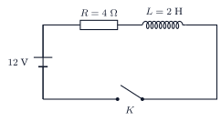
The switch \(K\) is closed at \(t = 0\). Take \(e^{-1} = 0.37\).
Find the time constant and the final current.
Find the current and the rate of change of current just after closing.
Find the current at \(t = 0.5\) s.
Answer(i) \(0.5\) s; \(3\) A (ii) \(0\); \(6\) A/s (iii) \(1.9\) A
Solution
\(\tau = \dfrac{L}{R} = \dfrac{2}{4} = 0.5\) s. Final current \(= \dfrac{E}{R} = 3\) A.
\(I = 0\). Then \(E = L\dfrac{dI}{dt}\), so \(\dfrac{dI}{dt} = \dfrac{12}{2} = 6\) A/s.
Why is the current zero at the instant the switch is closed, although the battery is connected?
Answerback emf equals \(E\) at \(t = 0\)
Solution
The inductor opposes any change of current. At the instant of closing, its back emf \(L\dfrac{dI}{dt}\) equals the full battery voltage, leaving nothing to drive current through \(R\). The current starts from zero and grows as the back emf falls.
How did it go?
Q28
What does the inductor behave like a long time after the switch is closed? What is the voltage across it then?
Answera plain wire; zero
Solution
Once the current is steady, \(\dfrac{dI}{dt} = 0\) and the inductor's emf is zero: it behaves as a plain piece of wire (or its own small resistance). The whole battery voltage then appears across \(R\).
How did it go?
Q29
For the circuit of Q2, find the time at which the current reaches half its final value. Take \(\ln 2 = 0.69\).
Answer\(0.35\) s
Solution
\(\dfrac{1}{2} = 1 - e^{-t/\tau}\), so \(e^{-t/\tau} = \dfrac{1}{2}\) and \(t = \tau\ln 2 = 0.5 \times 0.69 \approx 0.35\) s.
How did it go?
Q30
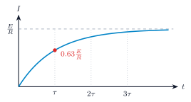
The graph shows the growing current.
What fraction of the final current flows at \(t = 2\tau\) and at \(t = 3\tau\)?
Why does the slope keep falling?
Answer(i) \(0.86\); \(0.95\) (ii) back emf falls as \(E - IR\) falls
Solution
\(1 - e^{-2} = 0.86\) and \(1 - e^{-3} = 0.95\) of the final current.
The slope is \(\dfrac{dI}{dt} = \dfrac{E - IR}{L}\). As \(I\) grows, the voltage left for the inductor, \(E - IR\), shrinks, so the current rises more and more slowly.
How did it go?
Q31
For the circuit of Q2 at \(t = 0.5\) s, find the voltage across the inductor and across the resistor. Check that they add to \(12\) V.
Answer\(4.4\) V; \(7.6\) V
Solution
\(V_L = L\dfrac{dI}{dt} = Ee^{-t/\tau} = 12 \times 0.37 \approx 4.4\) V. \(V_R = IR = 1.9 \times 4 \approx 7.6\) V. Sum \(\approx 12\) V, as the loop equation requires.
How did it go?
Q32
Find the energy stored in the inductor of Q2 when the current is steady. Find also the rate at which energy is being stored at \(t = 0.5\) s.
Answer\(9\) J; \(\approx 8.4\) W
Solution
Final: \(U = \dfrac{1}{2}LI^2 = \dfrac{1}{2} \times 2 \times 9 = 9\) J. At \(t = 0.5\) s the power into the inductor is \(V_LI = 4.4 \times 1.9 \approx 8.4\) W.
How did it go?
Decay of current
Q33
A current \(I_0\) flows through \(L\) and \(R\) when the battery is suddenly replaced by a plain wire. Write the loop equation and show that \(I = I_0e^{-t/\tau}\).
Answer\(0 = IR + L\frac{dI}{dt}\)
Solution
With no source, \(IR + L\dfrac{dI}{dt} = 0\), so \(\dfrac{dI}{I} = -\dfrac{R}{L}dt\). Integrating from \(I_0\) at \(t = 0\): \(\ln\dfrac{I}{I_0} = -\dfrac{t}{\tau}\), so \(I = I_0e^{-t/\tau}\) with \(\tau = \dfrac{L}{R}\). The inductor's emf now drives the current, keeping it going while it decays.
How did it go?
Q34
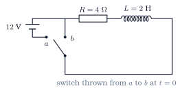
The current has reached \(3\) A when the switch is thrown from \(a\) to \(b\). Take \(e^{-1} = 0.37\) and \(e^{-2} = 0.14\).
Find the current at \(t = 0.5\) s.
Find the current at \(t = 1\) s.
Answer(i) \(1.1\) A (ii) \(0.42\) A
Solution
\(\tau = 0.5\) s, so \(t = \tau\): \(I = 3e^{-1} \approx 1.1\) A.
\(t = 2\tau\): \(I = 3e^{-2} \approx 0.42\) A.
How did it go?
Q35
Where does the energy \(\frac{1}{2}LI_0^2\) go during the decay in Q10? Find the total heat produced.
Answerheat in \(R\); \(9\) J
Solution
It is dissipated as heat in the resistor as the current dies away. Total heat \(= \int I^2R\,dt = \dfrac{1}{2}LI_0^2 = \dfrac{1}{2} \times 2 \times 9 = 9\) J.
How did it go?
Q36
In Q10, after what time has the current fallen to \(10\%\) of its initial value? Take \(\ln 10 = 2.3\).
Answer\(1.15\) s
Solution
\(e^{-t/\tau} = 0.1\), so \(t = \tau\ln 10 = 0.5 \times 2.3 = 1.15\) s.
How did it go?
Q37
The resistor in Q10 is replaced by \(8\) Ω before the switch is thrown. How does the decay change?
Answer\(\tau = 0.25\) s, twice as fast
Solution
\(\tau = \dfrac{L}{R} = \dfrac{2}{8} = 0.25\) s: the current decays twice as fast. The same energy \(9\) J is dissipated, but in a shorter time.
How did it go?
Q38
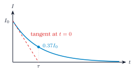
Show that the tangent to the decay curve at \(t = 0\) meets the time axis at \(t = \tau\).
Answerslope \(-\frac{I_0}{\tau}\) at \(t = 0\)
Solution
\(I = I_0e^{-t/\tau}\), so \(\dfrac{dI}{dt} = -\dfrac{I_0}{\tau}e^{-t/\tau}\), which at \(t = 0\) is \(-\dfrac{I_0}{\tau}\). The tangent line is \(I = I_0 - \dfrac{I_0}{\tau}t\), which reaches zero at \(t = \tau\). This gives a quick way to read \(\tau\) off a graph.
How did it go?
Instants
Q39
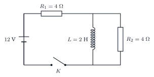
The switch \(K\) is closed at \(t = 0\).
Find the current from the battery just after closing.
Find the current from the battery a long time later.
Answer(i) \(1.5\) A (ii) \(3\) A
Solution
Just after closing, the inductor carries no current and acts as an open branch. The battery sees \(R_1 + R_2 = 8\) Ω: \(I = \dfrac{12}{8} = 1.5\) A.
Finally the inductor is a short across \(R_2\), so the battery sees only \(R_1\): \(I = \dfrac{12}{4} = 3\) A.
How did it go?
Q40
For the circuit of Q15, find the current through the inductor and through \(R_2\) (i) just after closing, (ii) a long time later.
Answer(i) \(0\); \(1.5\) A (ii) \(3\) A; \(0\)
Solution
(i) Inductor \(0\), \(R_2\) carries the full \(1.5\) A. (ii) The inductor short-circuits \(R_2\): inductor \(3\) A, \(R_2\) zero.
How did it go?
Q41
The switch of Q15 is opened after the currents have settled. Find the current through \(R_2\) just after opening, and the voltage across \(R_2\).
Answer\(3\) A; \(12\) V
Solution
The inductor's current of \(3\) A cannot change instantly. With the battery branch open, it must flow round the loop of \(L\) and \(R_2\). So \(R_2\) carries \(3\) A, now in the opposite direction to before. Voltage across \(R_2\): \(3 \times 4 = 12\) V.
How did it go?
Q42
Find the time constant of the decay in Q17.
Answer\(0.5\) s
Solution
The decay loop contains only \(L\) and \(R_2\): \(\tau = \dfrac{L}{R_2} = \dfrac{2}{4} = 0.5\) s.
How did it go?
Q43
Why can the current through an inductor not jump suddenly, while the voltage across it can?
Answera jump in \(I\) needs infinite \(L\frac{dI}{dt}\)
Solution
A sudden jump in current would mean an infinite \(\dfrac{dI}{dt}\) and an infinite back emf \(L\dfrac{dI}{dt}\), which no finite source can supply. The current therefore changes smoothly. The voltage across the inductor is \(L\dfrac{dI}{dt}\), which can change abruptly when the circuit is switched, as when the switch in Q17 is opened.
How did it go?
Small situations
Q44
Find the time constant of a \(50\) mH inductor in series with \(10\) Ω.
A coil of \(0.1\) H and \(2\) Ω is connected across \(6\) V. Find the final current, the time constant, and the current after \(0.05\) s.
Answer\(3\) A; \(0.05\) s; \(1.9\) A
Solution
Final \(I = \dfrac{6}{2} = 3\) A. \(\tau = \dfrac{0.1}{2} = 0.05\) s. At \(t = \tau\): \(I = 3(1 - 0.37) \approx 1.9\) A.
How did it go?
Q46
Show that \(\frac{L}{R}\) has the dimensions of time.
Answer\(\frac{[V\,s/A]}{[V/A]} = [s]\)
Solution
\(L\) has units of V s/A (from \(\varepsilon = L\dfrac{dI}{dt}\)) and \(R\) has units of V/A. Their ratio is \(\dfrac{\text{V s/A}}{\text{V/A}} = \) s, a time.
How did it go?
Q47
A \(10\) V battery is connected to a \(0.5\) H inductor of negligible resistance. Find the initial rate of rise of the current.
Answer\(20\) A/s
Solution
At \(t = 0\) the whole \(10\) V is across the inductor: \(\dfrac{dI}{dt} = \dfrac{E}{L} = \dfrac{10}{0.5} = 20\) A/s.
How did it go?
Q48
Verify by substitution that \(I = \frac{E}{R}\left(1 - e^{-Rt/L}\right)\) satisfies \(E = IR + L\frac{dI}{dt}\).
Answer\(L\frac{dI}{dt} = Ee^{-Rt/L}\); sum with \(IR\) is \(E\)
Solution
\(IR = E\left(1 - e^{-Rt/L}\right)\). \(\dfrac{dI}{dt} = \dfrac{E}{R}\cdot\dfrac{R}{L}e^{-Rt/L} = \dfrac{E}{L}e^{-Rt/L}\), so \(L\dfrac{dI}{dt} = Ee^{-Rt/L}\). Adding: \(IR + L\dfrac{dI}{dt} = E - Ee^{-Rt/L} + Ee^{-Rt/L} = E\). It also gives \(I = 0\) at \(t = 0\), as required.